2-Photon Functional Imaging

Since its introduction in 1990 (Denk et al., 1990), 2-Photon microscopy is the standard technique for functional imaging. Its superior Z-resolution has proven to be particularly useful for its application in the vertebrate retina and in the fly visual system, since it avoids unwanted out-of-focus excitation of photoreceptors that are in the vicinity of the neurons one records from. In conjunction with genetically encoded Calcium indicators such as GCaMP5 (Akerboom et al., 2012), 2-Photon Calcium imaging has become the method of choice to record the visual responses of small columnar neurons in the fly visual system that are inaccessible to electrophysiological recording methods. As another indicator of neuronal activity, the release of neurotransmitters such as Glutamate can be visualized (Marvin et al., 2013; Richter et al., 2018). This approach has the advantage that signals can be resolved at a high temporal resolution.

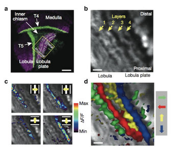
a Confocal image of the optic lobe of a driver line giving rise to expression in T4 and T5 cells, shown in a horizontal cross section (from Schnell et al, 2012). Neurons are marked in green (Kir2.1-EGFP labeled), while the neuropile is stained in red by an antibody against the postsynaptic protein Dlg. Scale bar = 20 mm. b 2-Photon image of the lobula plate of a fly expressing GCaMP5 under control of the same driver line. Scale bar = 5 mm. The size and orientation of the image approximately corresponds to the yellow square in c. c Relative fluorescence changes (DF/F) obtained during 4 sec grating motion along the four cardinal directions, overlaid on the grey-scale image. Each motion direction leads to activity in a different layer. Minimum and maximum DF/F values were 0.3 and 1.0 (horizontal motion), and 0.15 and 0.6 (vertical motion). d Compound representation of the results obtained from the same set of experiments. Scale bar = 5 mm.
2-Photon Calcium imaging allowed characterizing, for the first time, the visual response properties of T4 and T5 cells in the fly visual system (Maisak et al., 2013). We found that specific subpopulations of T4 and T5 cells are directionally tuned to one of the four cardinal directions; that is, front-to-back, back-to-front, upwards and downwards. Depending on their preferred direction, T4 and T5 cells terminate in specific sublayers of the lobula plate. While T4 and T5 cells show the same temporal frequency tuning, they functionally segregate with respect to contrast polarity: whereas T4 cells selectively respond to moving brightness increments (ON edges), T5 cells only respond to moving brightness decrements (OFF edges). Thus, starting with L1 and L2, the visual input is split into separate ON and OFF pathways, and motion along all four cardinal directions is computed separately within each pathway. The output of these eight different motion detectors is then sorted such that ON (T4) and OFF (T5) motion detectors with the same directional tuning converge in the same layer of the lobula plate, jointly providing the input to downstream circuits and motion-driven behaviors.

a Schematic of vertical (left) and horizontal (right) white-noise stimulus illustrated by three frames. b Terminals of Mi12 neurons expressing the genetically encoded calcium indicator GCaMP6f. Regions of interest (ROIs) for the analysis of calcium indicator fluorescence changes encompass single terminals. c time course of the fluorescence change. d Average aligned spatiotemporal receptive field of all M1 cells from b for a white-noise stimulus consisting of horizontal bars. Along the vertical axis, the center-surround structure of the ON-center receptive field is visible in the heat color code (vertical dashed line at the time of the peak of the response). The section along the time axis through the receptive field center reveals the temporal impulse response. e Spatial receptive field of Mi1
To precisely map the receptive fields of the input elements to T4- and T5-cells, a one-dimensional white-noise stimulus consisting of 2.8 deg wide horizontal or vertical bars can be used a. The spatiotemporal receptive fields are then determined from the neuron’s calcium response by reverse correlation. The temporal component of the spatiotemporal receptive field reflects the temporal filtering properties of the neuron (d, Temp impulse response). The spatial components of these are the one-dimensional horizontal and vertical projections of the underlying 2-dimensional spatial receptive field of the cell e.
References
Akerboom, J. et al. Optimization of a GCaMP calcium indicator for neural activity imaging. J. Neurosci. 32, 13819–13840 (2012).
Arenz A, Drews MS, Richter FG, Ammer G, Borst A. The temporal tuning of the Drosophila motion detectors is determined by the dynamics of their input elements. Curr Biol 27: 929-944 (2017).
Denk, W., Strickler, J. H. & Webb, W. W. Two-photon laser scanning fluorescence microscopy. Science 248, 73–76 (1990).
Maisak, M. S. et al. A directional tuning map of Drosophila elementary motion detectors. Nature 500, 212–216 (2013).
Marvin JS, Borghuis BG, Tian L, Cichon J, Harnett MT, Akerboom J, Gordus A, et al. An optimized fluorescent probe for visualizing glutamate neurotransmission. Nat Methods 10(2):162-170 (2013).
Richter FG, Fendl S, Haag J, Drews MS, Borst A. Glutamate signaling in the fly visual system. iScience 7:85-95 (2018.)


